|
Focus & Rangefinder Adjustment |
|
Focus, or inability to get correct focus is a major reason for rangefinder camera failure. Two camera faults which lead to bad focus are incorrect lens register and misadjusted rangefinders. Lens register (also known as “lens working distance”) refers to the fixed distance from the lens mount surface flange to the focal plane (ie, the film’s surface). This distance is standard for all LTM rangefinder cameras, and is critical since all lenses were designed to focus correctly with this value in consideration. For the FED and Zorki (and all Leica Screw Mount derived cameras), this value is exactly 28,8 mm with a tolerance of only +/- 0,02 mm. Any deviation greater than this tolerance will lead to bad focus, and therefore, unsharp images. |
|
IDENTIFY YOUR CAMERA FIRST. Very early prewar FED (such as those with „NKVD“-markings) did not have standard lens focus registers. The values varied greatly from camera to camera, and each camera had its lens calibrated specifically for it. Other lenses won’t likely be able to focus correctly on this cameras. If you suspect that your prewar FED doesn’t have its original lens, you can adjust focus register to standard 28,8mm, using the method given below. The lens can then be adjusted so that it will have the 28,8mm register as well.
Later FED and Zorki were supposed to have standard registers. However, I found that this wasn’t really the case. Of the many samples I’ve received, only two have the correct measure. Measure the cameras’ respective lens registers and adjust accordingly.
Very late FED 1 “g” whose s/n are above 450 xxx (basing from the samples I have) are likely found with correct lens registers. Their lens mount are also Leitz–correct (thread entry points and stopping positions agree with the Leitz specs).
There are four places where parts should be adjusted or tweaked to calibrate the camera’s RF and focusing system.. The optical wedge found in one of the rangefinder windows for vertical RF image alignment. The rangefinder screw for horizontal RF image alignment at infinity. The rangefinder sensor head for horizontal RF image alignment at minimum distances. And the lens mount for correct focus register or lens working distance. |
|
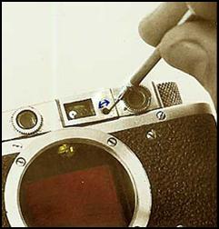
VERTICAL RF IMAGE ADJUSTMENT: Remove the left rangefinder bezel to expose the optical wedge collar. The collar has two notches which can be used to turn it until vertical RF alignment is achieved. This should be done preferably after horizontal RF image alignment is done. The optical wedge collar may often be found glued onto its mount. This will make turning impossible or difficult. The glue can be dissolved by placing a cotton wad saturated with alcohol or acetone on the wedge’s ring. Note too, that adjusting vertical image alignment can affect horizontal alignment, and may require readjusting the rangefinder screw. |
|
HORIZONTAL RF IMAGE ADJUSTMENT(INFINITY): Remove the large screw next to the VF window to access the RF adjustment screw. This is a tiny screw found in the hole covered by the large screw next to the VF port. Point the camera towards a very distant object and set the lens to infinity focus. BE SURE THAT THE LENS IS REALLY SET AT ITS INFINITY MARK (See note below)
If the RF image does not line up or goes beyond at this setting, the RF is out of sync. Using a tiny 1,2 mm screw driver, turn the screw inside (quite hard to see) in very minute increments. Check the RF image alignment by pointing the camera to the “infinity’ target to see if the images lineup. |
|
NOTICE! Some collapsible Industar 22 / 50 and FED-50 lenses can move BEYOND the Infinity mark of the scale. When calibrating the RF for infinity focus MAKE SURE that the distance pointer is at infinity. Many of these lenses lock at a point beyond the infinity mark. |
|
If the image appears to be „short“ of lining up, give the RF adjustment screw a clockwise turn. If the image goes past the other image at infinity, give the screw a counterclockwise turn. How much to turn depends on how short or how far the moving image is from the other incident RF image |
|
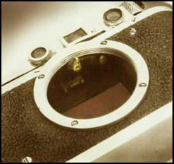
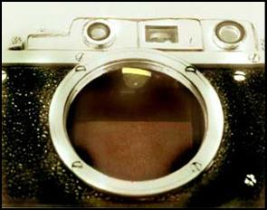
.UNLIKE THE LEICA, FED AND ZORKI REQUIRE ANOTHER ADJUSTMENT FOR HORIZONTAL ALIGNMENT AT CLOSE DISTANCE FOCUS. Adjusting the RF so that its images coincide at infinity alone will not guarantee its accuracy at short distances. The RF is adjusted for the near range through the RF sensor head found at the tip of the camera’s RF arm. FED and Zorki RF sensor heads look different, and both are pivoted to allow calibration. |
|
Left, FED RF sensor. Right, Zorki RF sensor. In later models of both cameras, the RF sensors used the sloped shape found in the Zorki. |
|
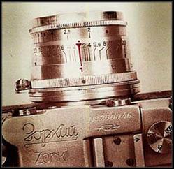
THIS IS AN IMPORTANT ADJUSTMENT STEP. HORIZONTAL ALIGNMENT AT MINIMUM DISTANCE: Place the camera on a tripod. Draw a cross on a piece of paper and stick this on the wall– this will be the focus target. Set the camera from the target so that its back is exactly 1 metre away. Focus the lens until the RF images coincide. Read the value given on the lens’ focusing scale: its index mark should point exactly at „1m” If the scale reads differently, and the index is off by more than 0,5mm from the „1“ mark, the rangefinder is still incorrect. Focus in this case will be off from minimum to around 3 metres. Short distance focus is more critical. This adjustment procedure isn’t done with Leica and other Leica-derived cameras. |
|
Left picture shows lens focused at 1 metre. Index mark should point EXACTLY at the 1 m mark. A properly adusted RF sensor head will make the lens distance scale read this way when the RF is focused at the 1 metre wall target.
If the focus index mark points at the distance closer than 1 metre, the sensor head should be “turned up” It should be turned in such a way that its point juts farther out. On the other hand, it the index mark indicates a distance farther than 1 metre, the RF tip should be “turned down”, or moved so that its point is retracted a bit. The sensor head is usually difficult to turn |
|
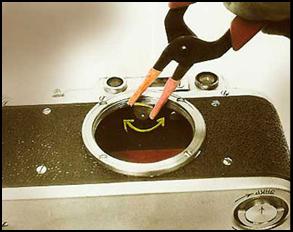
Use a small pair of pliers to turn the sensor head. Line the jaws with heat-shrink rubber tubing to protect the head. In the photo, a clockwise turn „raises“ the tip, and a counter clockwise turn “lowers” it. Do this by trial and error until the lens indicates the correct distance. IT MAY BE NECESSARY to check infinity focus as well after each adjustment in this procedure. Displacing the tip may affect the RF adjustment at infinity. |
|
The RF can be considered correctly adjusted if its images align at infinity and gives correct measurements at 1M. To prevent upsetting the tip’s position, place a drop of shellac glue or cyanoacrylate cement on the part where it touches the RF arm. Improper lens mounting/dismounting (ie, with the lens set at infinity and its RF cam jutting out from the rear) will upset the rf sensor’s adjustment. |
|
! |
|
! |